#include <LiquidCrystal_I2C.h>
LiquidCrystal_I2C lcd(0x3F,16,2);
//显示字符
#if defined(ARDUINO) && ARDUINO >= 100
#define printByte(args) write(args);
#else
#define printByte(args) print(args,BYTE);
#endif
//要显示的汉字编码,定义为一个数组
uint8_t dian[8]= {0x04,0x1F,0x15,0x1F,0x15,0x1F,0x04,0x07,};//电
uint8_t ya[8]= {0x0F,0x08,0x0A,0x0F,0x0A,0x0B,0x0A,0x17,};//压
uint8_t fu[8]={ 0x10,0x1C,0x14,0x04,0x1F,0x15,0x0A,0x11,};//负
uint8_t bat[8]={ 0x0E,0x1F,0x11,0x1F,0x1F,0x1F,0x1F,0x1F,};//
void setup(){
lcd.init(); //初始化LCD
lcd.backlight(); //打开背光
//创建新字符,将每个数组映射为一个字符,分别命名为0,1,2,3,4
lcd.createChar(0, bat);
//将字符显示到光标所在位
lcd.setCursor(0,0);
lcd.printByte(0);
lcd.setCursor(1,0);
lcd.print("13.8V");
}
void loop() {
// put your main code here, to run repeatedly:
}
//--------------------------------------------
电池
uint8_t bat[8]={ 0x0E,0x1F,0x11,0x1F,0x1F,0x1F,0x1F,0x1F,};//
闪电
uint8_t A[8]= { 0x00,0x02,0x04,0x08,0x1F,0x02,0x04,0x08,}
太阳能板
uint8_t solar[8]= { 0x1F,0x15,0x1F,0x15,0x1F,0x15,0x1F,0x00,};
2018年5月10日星期四
2018年4月20日星期五
lcd 菜单【测试】
#include <Bounce2.h>
#include <Wire.h>
#include <LiquidCrystal_I2C.h>
Bounce Mode =Bounce(5,50);
Bounce Select =Bounce(6,50);
int page=1;
int page2state=1;
//create an object called lcd, with address 0x38, wich is a display with 4 lines and 20 chars per line
LiquidCrystal_I2C lcd(0x20,16,2);
void setup()
{
pinMode(13,HIGH);
lcd.init();
lcd.setBacklight(HIGH);
lcd.setCursor(4,0);
lcd.print("Welcomes");
lcd.setCursor(3,1);
lcd.print("MPPT Solar");
delay(1000);
lcd.clear();
}
void loop()
{
digitalWrite(13,HIGH);
test();
SelectButton();
}
void test()
{
if(Mode.update()==true && Mode.read()==HIGH)
{
lcd.clear();
if(page==1);
{
page++;
}
if(page>3)
{
page=1;
}
}
switch(page)
{
case 1:
lcd.setCursor(0, 0);
lcd.print("Voltage:");
lcd.print("");
lcd.print("14.4");
lcd.print("V");
lcd.setCursor(0,1);
lcd.print("Amps:");
lcd.print("");
break;
case 2:
lcd.setCursor(0, 0);
lcd.print("Load 1");
lcd.setCursor(1,1);
lcd.print("ON");
lcd.setCursor(5,1);
lcd.print("OFF");
break;
case 3:
lcd.setCursor(0, 0);
lcd.print("page3");
break;
}
}
void SelectButton()
{
if(Select.update()==true && Select.read()==HIGH)
{
lcd.clear();
if(page2state==1)
{
page2state=0;
lcd.setCursor(0, 0);
lcd.print("Load 1 ");
lcd.setCursor(4,1);
lcd.print(">OFF");
lcd.setCursor(1,1);
lcd.print("ON");
}
else if(page2state==0)
{
page2state=1;
lcd.setCursor(0, 0);
lcd.print("page2");
lcd.setCursor(0,1);
lcd.print(">ON");
lcd.setCursor(5,1);
lcd.print("OFF");
}
}
}
LCD1602显示汉字
//LCD1602显示5*8点阵汉字程序,显示“上午下雨了”5个汉字
#include <Wire.h>  //加载Wire通讯库
#include <LiquidCrystal_I2C.h>  //加载液晶屏库
LiquidCrystal_I2C lcd(0x27,16,2);  // 设 LCD的地址为0x27,16列2行

//显示字符
#if defined(ARDUINO) && ARDUINO >= 100
#define printByte(args)  write(args);
#else
#define printByte(args)  print(args,BYTE);
#endif

//要显示的汉字编码,定义为一个数组
uint8_t shang[8]= {0x04,0x04,0x04,0x07,0x04,0x04,0x04,0x1F,};//上
uint8_t wu[8]= {0x08,0x08,0x0E,0x14,0x04,0x1F,0x04,0x04,};//午
uint8_t xia[8] = {0x1F,0x04,0x04,0x06,0x05,0x04,0x04,0x04,};//下
uint8_t yu[8] = {0x1F,0x04,0x1F,0x15,0x1F,0x15,0x1F,0x15,};//雨
uint8_t le[8] = {0x1F,0x01,0x02,0x04,0x04,0x04,0x04,0x0C,};//了

void setup(){
  lcd.init();     //初始化LCD
  lcd.backlight(); //打开背光

//创建新字符,将每个数组映射为一个字符,分别命名为0,1,2,3,4
  lcd.createChar(0, shang);
  lcd.createChar(1, wu);
  lcd.createChar(2, xia);
  lcd.createChar(3, yu);
  lcd.createChar(4, le);
 //将字符显示到光标所在位
  lcd.setCursor(0,0);
  lcd.printByte(0);
  lcd.printByte(1);
  lcd.printByte(2);
  lcd.printByte(3);
  lcd.printByte(4);
  }
void loop(){
}
2018年4月19日星期四
Arduino 蓄电池脉冲源码
int periodTime =millis() , PluseStatus = 0 ;
if ( PluseStatus == 0 && millis() - periodTime >= 1000 )
{
periodTime = millis();
PluseStatus = 1 ;
digitalWrite ( PluseCharging , PluseStatus ) ;
}
if ( PluseStatus == 1 && millis() - periodTime >= 3000 )
{
periodTime = millis();
PluseStatus = 0 ;
digitalWrite ( PluseCharging , PluseStatus ) ;
}
//periodTime 间隔
2018年4月17日星期二
【很冷的知識】analogWrite怎麼做PWM輸出?改PWM頻率,定时器相關)
【很冷的知識】analogWrite怎麼做PWM輸出?改PWM頻率,定时器相關)
tsaiwn 高级会员 2015-3-17 12:12
43888
本帖最后由 tsaiwn 于 2015-3-17 16:39 编辑
大家都知道在 Arduino UNO 有六支 pin 可以使用 analogWrite( )做 PWM 輸出,
在板子上 pin 旁邊標示有 "~" 符號, analogWrite( ) 可以用來產生模擬電壓,
很多人一定很好奇那是怎麼做到的 ?
首先來看看 PWM 模擬電壓的原理, 這在官網上就有解說了:
http://arduino.cc/en/Tutorial/SecretsOfArduinoPWM
所謂的 PWM 全稱是 Pulse-Width Modulation (PWM), 其實這也沒啥學問,
就是對 GPIO 腳位不斷的切換 "有電" "沒電",
每秒鐘循環幾次即為其 Frequency(頻率),
每次"有電"時間佔一個循環的百分比稱為其佔空比(Duty cycle);
以下是官網上的模擬範例:
int pin = 13;
void setup() {
pinMode(pin, OUTPUT);
}
void loop(){
digitalWrite(pin, HIGH);
delayMicroseconds(100); // Approximately 10% duty cycle @ 1KHz
digitalWrite(pin, LOW);
delayMicroseconds(1000 - 100);
}
這個範例中, 一個循環是 1000 us = 1ms, 所以一秒循環 1000次, 因此 Frequency 是 1 KHz,
每個循環中, 有電的比率是 100/1000 * 100% = 10%, 所以 duty cycle (佔空比)為 10%;
這樣就可以模擬出 5Volt x 10% = 0.5 Volt 的電壓!
如果真的這樣做, 有好處也有壞處, 官網上已經說了:
好處是任一支 pin 都可這樣用, 包括 Pint 0 到 Pin 13, 以及 Pin A0 到 A5 共 20支 pin 都可以!
壞處卻更多, 首先就是頻率(Frequency)和佔空比(duty cycle)可能受中斷(Interrup)的影響變成不是很準確 !!
最大的壞處是, 在某支 pin 做 PWM 輸出期間都沒辦法做別的事情 !!
既然說這只是示範可以這樣做, 在 Arduino 當然不可能是這麼做,
那 Arduino 是怎麼做的呢?
就是透過 Timer 計時器直接控制 pin 做 PWM 輸出, Arduino UNO 的 MCU 有三個 timer,
其中 timer0 控制 pin 5, pin 6; timer1 控制 pin 9, pin 10; timer 2 控制 pin 11, pin 3;
所以, 我們可以對這些 pin 用 analogWrite(pin, val); 輸出 0 到 255 的 val 值到 pin ;
如果輸出 val 是 0, 它會偷偷直接改用 digitalWrite(pin, 0); 輸出,
如果 val 是 255, 也是會偷偷直接改用 digitalWrite(pin, 1); 輸出!
如果 val 是 1 到 254, 則會下命令請 pin 腳對應的 timer 計時器(定時器)幫忙!!
How ?
首先要知道 timer 的基本知識:
(1)每個 timer 一定有個 counter, 例如 timer0 的TCNT0, timer1 的TCNT1, timer2 的TCNT2;
該 counter 一定是每個 tick 會加 1, 每個 tick 通常是把 CPU 的 clock 拿來經過一個除頻電路,
然後給 timer 使用; Arduino UNO 採用 AVR ATmega328 MCU, 且 clock Rate 是 16MHz,
每個 timer 的除頻 Prescaler 是獨立設定的, 通常可以設 1, 2, 4, 8, 64, 256, or 1024 等,
這必須看 MCU 的 datasheet.
(2)每個 timer 通常提供許多 mode 運作模式, 例如 counter 溢出(Overflow)或Rollover歸零時產生中斷,
或 TCNT? 達到某個值時產生中斷等, Arduino ATmega328 的 timer 有 16種 mode, 許多 Mode 是與 PWM 有關;
要設定 timer 的 Mode 可以透過修改 timer 的控制暫存器, 例如 TCCR?A, TCCR?B, 注意以 ATmega328 為例, TCCR?A 和 TCCR?B 要合起來用, 此處的 A, B 與 channel A, channel B 無關!!
(3)每個 timer 通常有比較暫存器(Compare Register), 當 TCNT? 值與該些比較暫存器相同時可以做某事,
不一定是對 CPU 產生中斷! Arduino 每個 timer 有兩個比較暫存器, 分別命名 OCR?A 和 OCR?B,
其中 ? 是 0, 1, 2 分別對應到 timer0, timer1, 和 timer2 這三個計時器.
你可以先偷看 analogWrite( ) 的程序碼:
在你 Arduino IDE 下的 hardware\arduino\cores\arduino\wiring_analog.c
很簡單, 真正請 timer 幫忙只做三件事: a.找出對應的 port, b.設定控制暫存器, c.填入 analog的值到比較暫存器!
不過你會發現看不太懂, 因為還不知道硬體 timer 控制 PWM 運作方式與原理!
不想看 datasheet 可以參考這:
http://letsmakerobots.com/conten ... mers-and-interrupts
以Arduino UNO 的 timer1為例, 在 mode 5 (Fast PWM, 8 bit), 此時, TCNT1 從 0 數到 255, 然後又加 1 就變0, ...
通常從 255 (此 mode 的最大值)又加 1 變為 0 之時會產生 OVF 中斷(TIMSK1的TOIE1要 set), 不過這與 PWM 無關!
PWM 不是用 Interrupt 中斷請求做的, 不必麻煩 CPU, CPU 只要下命令給 timer, timer 就會照命令執行PWM工作 !!
PWM 是利用每個 timer 上的兩個"匹配符合輸出"暫存器(Compare Match Output) COM?A 和 COM?B;
(注意雖是 Compare Match Output, 但暫存器名稱是 COMxy 不是 CMOxy 喔 !)
在timer1 的 mode 5, 又稱 Fast PWM mode, (不過請注意 Arduino 的 init( ) 設定只有 timer0 用這, 另外 timer1 和 timer2 不是用這 mode),
這時可以把 1 到 254 之間的值放入 OCR1A 或 OCR1B 以便控制 pin 9 或 pin 10
的 PWM duty cycle, 1 到 254 分別對應到 (1+1)/256, .., (254+1)/256 的 duty cycle.
會 +1 是硬體電路設計上的關係, data sheet 上說:
Note that fast PWM holds the output high one cycle longer than the compare register value.
在 TCNT1 等於 0 之時, COM1A and/or COM1B 會輸出(當然要 TCCR1A 內的 COM1A1 and/or COM1B1 有set),
然後在 TCNT1 等於 OCR1A 則關閉 COM1A, 當 TCNT1 等於 OCR1B 則關閉 COM1B,
注意沒有立即關閉, 是延遲一個 tick 才關閉 ! 所以才會多加1, 因為一個循環是 256, 不是 255,如果不延遲加 1, 則輸出 val 是 254 時變成 254/256, 還差一點點, 所以犧牲 1/256, 就是沒有 1/256佔空比 !!
由於 Arduino 的 init( )把 timer1 的 Prescaler 設定為 64,
(參考在你 Arduino IDE 內的 hardware\arduino\cores\arduino\wiring.c )
且把 timer1 設定為 8-bit phase correct pwm mode, 所以其頻率是 490.196Hz, 不是 976.5625Hz;
所謂的 8-bit phase correct pwm mode, 意思是 TCNT? 從 0 數到 255, 接著又從 255 倒著數回 0,
那何時把 COM1A and/or COM1B 的輸出打開或關閉呢?
根據 datasheet, 在從 0 往上數, 碰到 OCR1A 時把 COM1A 關閉,
然後從 255 往回數, 數到 OCR1A 時把 COM1A 打開(有電); 對於 OCR1B 和 COM1B 也是這樣!
這使得 duty cycle (佔空比) 更準確, 也就是 val 1 ~ 254 分別對應到 1/255 到 254/255 的 duty cycle.
但是 Frequency 則不是除以 256, 是要除以 255 再除以 2, 於是: (注意是 255, 不是 256喔!)
Frequency = 16 MHz / 64 / 255 / 2 = 490.196Hz;
timer 2 也是在 init( )被設為 Prescaler 64 的 phase correct pwm (8-bit);
但是, timer0 雖然 Prescaler 也設 64, 但 PWM 是用 Fast PWM mode,
不使用 phase correct mode 是為了避免影響維護 millis( ) 的中斷 timer0 Overflow Interrupt,
即 ISR(TIMER0_OVF_vect) 這中斷處理程序, 否則 millis( ) 和 micros( ) 以及 delay() 都會受到影響 !!
因此 , timer0 控制的 PWM 其 Frequency 是 976.5625Hz,
16 MHz / 64 / 256 = 976.5625Hz
注意用 timer0 控制的pin 5, pin 6 之 PWM 的 duty cycle 無法是 1/256, 它是 0 再來就 2/256了!
結論:
timer0 控制 pin 5, pin 6, PWM 頻率 976.5625Hz, duty cycle可以 2/256 ~ 255/256 (對應 1 到254);
timer1 控制 pin 9, pin 10, PWM 頻率 490.196Hz, duty cycle 可以 1/255 ~ 254/255(對應 1 到254);
timer2 控制 pin 11, pin 3, PWM 頻率 與 duty cycle 跟 timer1 控制的相同 !!
Q: 那 PWM 的 Frequency 可不可以更改?
A: 可以, 偷改 timer 的 Prescaler 就可以達到更改 Frequency 的目的 !
但是, 千萬不要更改 timer0 的 Prescaler, 否則 millis( ) 和 micros( ) 以及 delay() 都會受到影響 !!!
以下是以 timer1 控制的 pin 9, pin 10 為例(注意兩個 pin 的頻率相同!)
在你的 setup( ) { 內, 寫如下兩句即可:
int fff = 3; // 可以是 1, 2, 3, 4, 5
TCCR1B = TCCR1B & 0xF8 | fff;
其中 fff 與對應頻率如下:
fff Prescaler Frequency
1 1 31372.549 Hz
2 8 3921.569
3 64 490.196 <--DEFAULT
4 256 122.549
5 1024 30.637 Hz
至於 timer2 控制的 pin 11 和 pin 3,
則在 setup( ) { 內寫:
TCCR2B = TCCR2B & 0xF8 | ?;
此處的 ? 可以有七種:
? Prescaler Frequency
1 1 31372.549 Hz
2 8 3921.569
3 32 980.392
4 64 490.196 <--DEFAULT
5 128 245.098
6 256 122.549
7 1024 30.637 Hz
如果你堅持要改 timer0 的 Prescaler, 以更改 pin 5, pin 6 的 PWM 頻率:
(注意 millis( ) 和 micros( ) 以及 delay() 都會受到影響 !! )
則在 setup( ) { 內寫:
TCCR0B = TCCR0B & 0xF8 | ?;
此處的 ? 可以有五種:
? Prescaler Frequency
1 1 362500 Hz
2 8 7812.5
3 64 976.5625 <--DEFAULT
4 256 244.140625
5 1024 61.03515625 Hz
參考:
http://playground.arduino.cc/Main/TimerPWMCheatsheet
http://www.atmel.com/Images/doc8161.pdf
按键开关led 带提示音


int led=3;
int state=LOW;
int buzzer=9;
Bounce btn = Bounce(2,50);
void setup()
{
pinMode(2,INPUT);
pinMode(9,OUTPUT);
pinMode(3,OUTPUT);
}
void loop()
{
if(btn.update()==true && btn.read()==HIGH)
{
tone(buzzer,1480,200);
if(state==LOW)
{
state=HIGH;
}
else
{
state=LOW;
}
digitalWrite(led,state);
}
}
2018年4月16日星期一
Arduino real time clock with DS1307
This post shows a simple real time clock and calendar example using an Arduino UNO board and DS1307 RTC chip where time and calendar are displayed on 1602 LCD screen and it can be set with two push buttons.
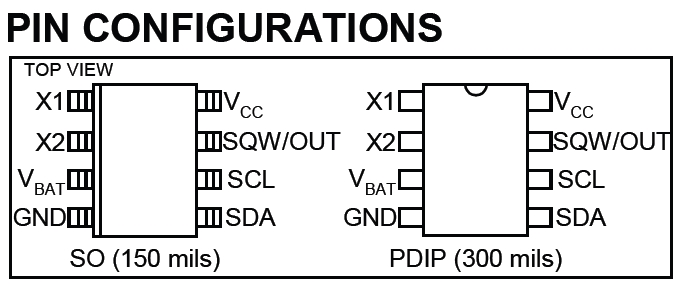
The DS1307 is an IC (integrated circuit) which has only 8 pins, it’s low cost, easy to use and it has the ability to count time and date in real time (more details are in the datasheet).
Hardware Required:
- Arduino board
- DS1307 RTC
- 16×2 LCD screen
- 32.768KHz crystal oscillator
- 2 x push button
- 2 x 10K ohm resistor
- 10K ohm variable resistor (or potentiometer)
- 330 ohm resistor
- 3V coin cell battery
- Breadboard
- Jumper wires
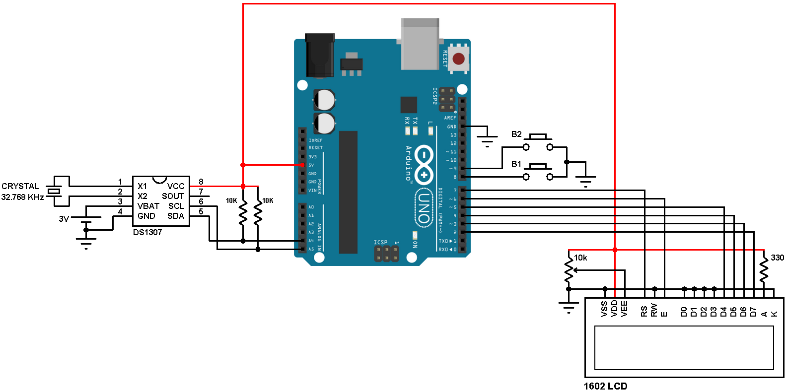
In the circuit there are 2 push buttons (B1 & B2) connected to pins 8 and 9 respectively, the two push buttons are used to set time date parameters (minutes, hours, date, month and year). Button B1 selects the parameter and B2 increments the selected parameter.
Arduino real time clock with DS1307 code:
The Arduino code below doesn’t use any library for the DS1307 RTC, the Wire library is for the communication between the Arduino and the DS1307 using I2C protocol.
The DS1307 works with BCD format only and to convert the BCD to decimal and vise versa I used the 2 lines below (example for minute):
// Convert BCD to decimal
minute = (minute >> 4) * 10 + (minute & 0x0F);
// Convert decimal to BCD
minute = ((minute / 10) << 4) + (minute % 10);
void DS1307_display() : displays time and calendar, before displaying time and calendar data are converted from BCD to decimal format.
void blink_parameter() : this small function works as a delay except that it is interrupted by the buttons B1 (connected to pin 8) and B2 (connected to pin 9). When called and without pressing any button the total time is 10 x 25ms = 250ms. With this function we can see the blinking of the selected parameter with a frequency of 2Hz. So a delay of 250ms comes after the print of the selected parameter and after that delay a 2 spaces is printed which makes the parameter disappears from the LCD and another 250ms delay comes after the print of the 2 spaces.The complete code is below.
---------------------------------------------------------------------------------------
// Real time clock and calendar with set buttons using DS1307 and Arduino
// include LCD library code
#include <LiquidCrystal.h>
// include Wire library code (needed for I2C protocol devices)
#include <Wire.h>
// LCD module connections (RS, E, D4, D5, D6, D7)
LiquidCrystal lcd(7, 6, 5, 4, 3, 2);
void setup() {
pinMode(8, INPUT_PULLUP); // button1 is connected to pin 8
pinMode(9, INPUT_PULLUP); // button2 is connected to pin 9
// set up the LCD's number of columns and rows
lcd.begin(16, 2);
Wire.begin(); // Join i2c bus
}
char Time[] = "TIME: : : ";
char Calendar[] = "DATE: / /20 ";
byte i, second, minute, hour, date, month, year;
void DS1307_display(){
// Convert BCD to decimal
second = (second >> 4) * 10 + (second & 0x0F);
minute = (minute >> 4) * 10 + (minute & 0x0F);
hour = (hour >> 4) * 10 + (hour & 0x0F);
date = (date >> 4) * 10 + (date & 0x0F);
month = (month >> 4) * 10 + (month & 0x0F);
year = (year >> 4) * 10 + (year & 0x0F);
// End conversion
Time[12] = second % 10 + 48;
Time[11] = second / 10 + 48;
Time[9] = minute % 10 + 48;
Time[8] = minute / 10 + 48;
Time[6] = hour % 10 + 48;
Time[5] = hour / 10 + 48;
Calendar[14] = year % 10 + 48;
Calendar[13] = year / 10 + 48;
Calendar[9] = month % 10 + 48;
Calendar[8] = month / 10 + 48;
Calendar[6] = date % 10 + 48;
Calendar[5] = date / 10 + 48;
lcd.setCursor(0, 0);
lcd.print(Time); // Display time
lcd.setCursor(0, 1);
lcd.print(Calendar); // Display calendar
}
void blink_parameter(){
byte j = 0;
while(j < 10 && digitalRead(8) && digitalRead(9)){
j++;
delay(25);
}
}
byte edit(byte x, byte y, byte parameter){
char text[3];
while(!digitalRead(8)); // Wait until button (pin #8) released
while(true){
while(!digitalRead(9)){ // If button (pin #9) is pressed
parameter++;
if(i == 0 && parameter > 23) // If hours > 23 ==> hours = 0
parameter = 0;
if(i == 1 && parameter > 59) // If minutes > 59 ==> minutes = 0
parameter = 0;
if(i == 2 && parameter > 31) // If date > 31 ==> date = 1
parameter = 1;
if(i == 3 && parameter > 12) // If month > 12 ==> month = 1
parameter = 1;
if(i == 4 && parameter > 99) // If year > 99 ==> year = 0
parameter = 0;
sprintf(text,"%02u", parameter);
lcd.setCursor(x, y);
lcd.print(text);
delay(200); // Wait 200ms
}
lcd.setCursor(x, y);
lcd.print(" "); // Display two spaces
blink_parameter();
sprintf(text,"%02u", parameter);
lcd.setCursor(x, y);
lcd.print(text);
blink_parameter();
if(!digitalRead(8)){ // If button (pin #8) is pressed
i++; // Increament 'i' for the next parameter
return parameter; // Return parameter value and exit
}
}
}
void loop() {
if(!digitalRead(8)){ // If button (pin #8) is pressed
i = 0;
hour = edit(5, 0, hour);
minute = edit(8, 0, minute);
date = edit(5, 1, date);
month = edit(8, 1, month);
year = edit(13, 1, year);
// Convert decimal to BCD
minute = ((minute / 10) << 4) + (minute % 10);
hour = ((hour / 10) << 4) + (hour % 10);
date = ((date / 10) << 4) + (date % 10);
month = ((month / 10) << 4) + (month % 10);
year = ((year / 10) << 4) + (year % 10);
// End conversion
// Write data to DS1307 RTC
Wire.beginTransmission(0x68); // Start I2C protocol with DS1307 address
Wire.write(0); // Send register address
Wire.write(0); // Reset sesonds and start oscillator
Wire.write(minute); // Write minute
Wire.write(hour); // Write hour
Wire.write(1); // Write day (not used)
Wire.write(date); // Write date
Wire.write(month); // Write month
Wire.write(year); // Write year
Wire.endTransmission(); // Stop transmission and release the I2C bus
delay(200); // Wait 200ms
}
Wire.beginTransmission(0x68); // Start I2C protocol with DS1307 address
Wire.write(0); // Send register address
Wire.endTransmission(false); // I2C restart
Wire.requestFrom(0x68, 7); // Request 7 bytes from DS1307 and release I2C bus at end of reading
second = Wire.read(); // Read seconds from register 0
minute = Wire.read(); // Read minuts from register 1
hour = Wire.read(); // Read hour from register 2
Wire.read(); // Read day from register 3 (not used)
date = Wire.read(); // Read date from register 4
month = Wire.read(); // Read month from register 5
year = Wire.read(); // Read year from register 6
DS1307_display(); // Diaplay time & calendar
delay(50); // Wait 50ms
}
---------------------------------------------------------------------------------------
LCD 1602 I2C背光无按键输入自动关闭

#include <Bounce2.h>
Bounce btn =Bounce(2,50);//宣告按键
Bounce btn =Bounce(2,50);//宣告按键
int LCDbacklight=LOW; //存储LCD背光状态
long previousMillis = 0;
long interval = 15000;
void setup() {
pinMode(2,INPUT);
}
void loop()
{
unsigned long currentMillis = millis(); //系统运行时间
unsigned long currentMillis = millis(); //系统运行时间
if(LCDbacklight==HIGH);
{
if(currentMillis - previousMillis > interval)
{
{
if(currentMillis - previousMillis > interval)
{
lcd.noBacklight(); //LCD背光关闭
LCDbacklight=LOW;
}
}
LCDbacklight=LOW;
}
}
if(btn.update()==true && btn.read()==HIGH)
{
previousMillis = currentMillis;
LCDbacklight=HIGH; //存储LCD背光状态
lcd.backlight();//打开LCD背光
}
LCD 没有按键输入自动熄屏幕 【调式】
#include <Bounce2.h>
Bounce btn =Bounce(2,50);
int led =13;
int ledstate=LOW;
long previousMillis = 0;
long interval = 1000;
int lcd=HIGH;
void setup() {
pinMode(2,INPUT);
pinMode(led,OUTPUT);
}
void loop() {
unsigned long currentMillis = millis();
if(lcd==LOW);
{
if(currentMillis - previousMillis > interval)
{
previousMillis = currentMillis;
ledstate=LOW;
digitalWrite(led,ledstate);
lcd=HIGH;
}
}
if(btn.update()==true && btn.read()==HIGH)
{
lcd=LOW;
if(ledstate==LOW)
{
ledstate=HIGH;
}
else
{
ledstate=LOW;
}
digitalWrite(led,ledstate);
}
}
2018年4月15日星期日
arduino 红外接收源码
#include <IRremote.h>
int RECV_PIN = 11;
int ledPin=12;
int ledState = LOW;
IRrecv irrecv(RECV_PIN);
decode_results results;
void setup()
{
Serial.begin(9600);
irrecv.enableIRIn();
Serial.println("Enabled IRin");
pinMode(ledPin,OUTPUT);
irrecv.blink13(true);
}
void loop() {
if (irrecv.decode(&results))
{
switch(results.value)
{
case 0xFF12ED:
if(ledState==LOW)
{
ledState=HIGH;
}
else
{
ledState=LOW;
}
digitalWrite(ledPin,ledState);
Serial.println(results.value, HEX);
delay(50);
irrecv.resume();
break;
case 0xFFFFFFF:
irrecv.resume();
return;
break;
}
}
}
2018年4月8日星期日
LCD1602汉字5*8点阵字库(for arduino) 持续更新
北={0x0A,0x0A,0x0A,0x1B,0x0A,0x0A,0x0A,0x1B,}
京={0x04,0x1F,0x0E,0x0A,0x0E,0x15,0x15,0x0C,}
市={0x04,0x1F,0x04,0x1F,0x15,0x15,0x15,0x04,}
和={0x08,0x13,0x0B,0x1F,0x0B,0x1F,0x1C,0x08,}
九={0x08,0x08,0x1E,0x0A,0x0A,0x0A,0x0A,0x13,}
小={0x04,0x04,0x15,0x15,0x15,0x15,0x04,0x0C,}
学={0x15,0x1F,0x11,0x0F,0x02,0x1F,0x04,0x0C,}
生={0x02,0x0A,0x0A,0x17,0x02,0x0F,0x02,0x0F,}
守={0x04,0x1F,0x11,0x02,0x1F,0x02,0x0A,0x06,}
则={0x1D,0x15,0x1F,0x1F,0x1F,0x0B,0x15,0x13,}
五={0x1E,0x08,0x08,0x1E,0x0A,0x0A,0x0A,0x1F,}
年={0x04,0x0C,0x0F,0x12,0x0F,0x0A,0x1F,0x02,}
王={0x1F,0x04,0x04,0x1F,0x04,0x04,0x04,0x1F,}
孚={0x1F,0x15,0x0E,0x02,0x04,0x1F,0x04,0x0C,}
吉={0x04,0x1F,0x04,0x1F,0x00,0x1F,0x11,0x1F,}
上={0x04,0x04,0x04,0x07,0x04,0x04,0x04,0x1F,}
下={0x1F,0x04,0x04,0x06,0x05,0x04,0x04,0x04,}
午={0x08,0x08,0x0E,0x14,0x04,0x1F,0x04,0x04,}
大={0x04,0x04,0x1F,0x04,0x04,0x0A,0x11,0x11,}
多={0x02,0x0F,0x05,0x1F,0x02,0x0F,0x05,0x1F,}
少={0x04,0x04,0x15,0x15,0x0D,0x02,0x04,0x18}
左={0x04,0x1F,0x04,0x08,0x17,0x02,0x02,0x0F,}
右={0x04,0x1F,0x04,0x08,0x1F,0x09,0x09,0x0F,}
天={0x0E,0x04,0x04,0x1F,0x04,0x0A,0x0A,0x11,}
气={0x08,0x17,0x06,0x00,0x0F,0x02,0x04,0x0F,}
云={0x00,0x0E,0x00,0x1F,0x08,0x0A,0x11,0x1D,}
雨={0x1F,0x04,0x1F,0x15,0x1F,0x15,0x1F,0x15,}
雷={0x1F,0x04,0x1F,0x15,0x04,0x1F,0x15,0x1F,}
闪={0x17,0x01,0x15,0x15,0x15,0x1B,0x11,0x13,}
电={0x04,0x1F,0x15,0x1F,0x15,0x1F,0x04,0x07,}
月={0x0F,0x09,0x0F,0x09,0x0F,0x09,0x09,0x13,}
日={0x00,0x1F,0x11,0x11,0x1F,0x11,0x11,0x1F,}
时={0x01,0x1D,0x17,0x1D,0x15,0x17,0x1D,0x03,}
分={0x0A,0x0A,0x11,0x00,0x1F,0x09,0x09,0x13,}
间={0x17,0x01,0x1F,0x1B,0x1F,0x1B,0x1F,0x11,}
问={0x17,0x01,0x11,0x1F,0x1B,0x1F,0x11,0x13,}
人={0x02,0x02,0x04,0x04,0x04,0x0A,0x0A,0x11,}
中={0x04,0x04,0x1F,0x15,0x15,0x1F,0x04,0x04,}
正={0x1F,0x04,0x04,0x07,0x14,0x14,0x14,0x1F,}
写={0x1F,0x11,0x0E,0x08,0x0F,0x01,0x1F,0x01,}
字={0x04,0x1F,0x11,0x0E,0x02,0x1F,0x04,0x0C,}
文={0x04,0x1F,0x0A,0x0A,0x0A,0x04,0x0A,0x11,}
件={0x06,0x0E,0x1A,0x0F,0x0A,0x0F,0x0A,0x0A,}
子={0x1F,0x02,0x04,0x04,0x1F,0x04,0x04,0x0C,}
了={0x1F,0x01,0x02,0x04,0x04,0x04,0x04,0x0C,}
点={0x04,0x07,0x04,0x1F,0x11,0x1F,0x00,0x15,}
阵={0x1A,0x1F,0x1A,0x16,0x1F,0x1A,0x17,0x12,}
库={0x04,0x1F,0x12,0x1F,0x17,0x1A,0x1F,0x12,}
电={0x04,0x1F,0x15,0x1F,0x15,0x1F,0x04,0x07,}
压={0x0F,0x08,0x0A,0x0F,0x0A,0x0B,0x0A,0x17,}
工={0x00,0x1F,0x04,0x04,0x04,0x04,0x04,0x1F,}
作={0x09,0x12,0x0B,0x0A,0x0B,0x0A,0x0B,0x0A,}
态={0x04,0x1F,0x04,0x0A,0x19,0x04,0x11,0x0F,}
第 1 页
5×8点阵汉字库
分={0x0A,0x0A,0x11,0x00,0x1F,0x09,0x09,0x13,}
开= {0x1F,0x0A,0x0A,0x0A,0x1F,0x0A,0x0A,0x12,}
关= {0x11,0x0A,0x1F,0x04,0x1F,0x04,0x0A,0x11,}
习={0x1F,0x01,0x11,0x0B,0x05,0x09,0x11,0x03,}
车={0x04,0x1F,0x08,0x12,0x1F,0x02,0x1F,0x02,}
东={0x04,0x1F,0x08,0x14,0x1F,0x04,0x15,0x0C,}
西={0x00,0x1F,0x0A,0x1F,0x1B,0x1B,0x11,0x1F,}
南={0x04,0x1F,0x04,0x1F,0x1B,0x15,0x1F,0x15,}
不={0x00,0x1F,0x04,0x08,0x16,0x05,0x04,0x04,}
有={0x04,0x1F,0x08,0x1F,0x09,0x0F,0x0F,0x09,}
出={0x04,0x15,0x15,0x1F,0x04,0x15,0x15,0x1F,}
完={0x04,0x1F,0x11,0x0E,0x00,0x1F,0x0A,0x1B,}
几={0x00,0x0E,0x0A,0x0A,0x0A,0x0A,0x0A,0x13,}
个= {0x04,0x04,0x0A,0x15,0x04,0x04,0x04,0x04,}
阳={0x18,0x1F,0x1D,0x17,0x1D,0x1D,0x17,0x10,}
光={0x04,0x15,0x04,0x1F,0x0A,0x0A,0x0A,0x1B,}
力={0x08,0x08,0x1F,0x09,0x09,0x09,0x09,0x13,}
艾={0x0A,0x1F,0x0A,0x11,0x0A,0x04,0x0A,0x11,}
可={0x00,0x1F,0x02,0x1E,0x16,0x1E,0x02,0x06,}
口={0x00,0x00,0x1F,0x11,0x11,0x11,0x1F,0x00,}
区={0x00,0x1E,0x10,0x1A,0x14,0x1A,0x10,0x1F,}
回={0x00,0x1F,0x11,0x1F,0x1B,0x1F,0x11,0x1F,}
去={0x04,0x1F,0x04,0x04,0x1F,0x0A,0x11,0x1E,}
玉={0x1F,0x04,0x04,0x1F,0x04,0x06,0x05,0x1F,}
于={0x1F,0x04,0x04,0x1F,0x04,0x04,0x14,0x0C,}
显={0x1F,0x11,0x1F,0x1F,0x0A,0x1B,0x0A,0x1F,}
示= {0x0E,0x00,0x1F,0x04,0x0E,0x15,0x04,0x0C,}
张={0x00,0x1A,0x0B,0x1A,0x17,0x1A,0x0B,0x1A,}
志={0x04,0x1F,0x04,0x1F,0x00,0x12,0x19,0x0E,}
忠={0x04,0x1F,0x15,0x1F,0x04,0x16,0x11,0x0E,}
首={0x0A,0x1F,0x04,0x1F,0x11,0x1F,0x11,0x1F,}
长={0x0A,0x0C,0x08,0x1F,0x08,0x0C,0x0A,0x0D,}
水={0x04,0x04,0x1D,0x06,0x0C,0x16,0x05,0x0C,}
平={0x1F,0x04,0x15,0x15,0x04,0x1F,0x04,0x04,}
行={0x08,0x0B,0x10,0x0B,0x19,0x09,0x09,0x0B,}
为= {0x14,0x04,0x1F,0x05,0x09,0x0B,0x09,0x1B,}
功={0x02,0x1E,0x0A,0x0F,0x0B,0x1D,0x05,0x0B,}
先={0x14,0x1E,0x14,0x04,0x1F,0x0A,0x0A,0x1B,}
后={0x01,0x0E,0x08,0x0F,0x08,0x0F,0x0D,0x17,}
击={0x04,0x1F,0x04,0x1F,0x04,0x15,0x15,0x1F,}
白={0x04,0x08,0x1F,0x09,0x0F,0x09,0x09,0x0F,}
毛={0x04,0x18,0x08,0x1E,0x08,0x1E,0x09,0x0F,}
女={0x08,0x0A,0x1F,0x0A,0x12,0x0A,0x04,0x0A,}
凡={0x0E,0x0A,0x0A,0x0E,0x0A,0x0A,0x0A,0x13,}
百={0x1F,0x04,0x08,0x1F,0x09,0x0F,0x09,0x0F,}
头={0x14,0x0C,0x04,0x1F,0x04,0x04,0x0A,0x11,}
手={0x01,0x1F,0x04,0x1F,0x04,0x1F,0x04,0x0C,}
书={0x0A,0x09,0x1E,0x0A,0x1F,0x09,0x09,0x0B,}
店={0x04,0x1F,0x14,0x16,0x14,0x1F,0x19,0x1F,}
甲={0x1F,0x15,0x1F,0x15,0x1F,0x04,0x04,0x04,}
乙={0x1F,0x01,0x02,0x04,0x08,0x10,0x11,0x0E,}
丙={0x1F,0x04,0x04,0x1F,0x15,0x1B,0x11,0x13,}
丁={ 0x1F,0x04,0x04,0x04,0x04,0x04,0x14,0x0C,}
空={0x04,0x1F,0x11,0x0A,0x11,0x0E,0x04,0x1F,}
万={0x1F,0x08,0x08,0x0F,0x09,0x09,0x09,0x13,}
第 2 页
5×8点阵汉字库
众={0x04,0x04,0x0A,0x11,0x0A,0x0A,0x15,0x00,}
创={0x09,0x09,0x15,0x03,0x1F,0x17,0x11,0x0D,}
业={0x0A,0x0A,0x1B,0x1B,0x1B,0x0A,0x0A,0x1F,}
上={0x04,0x04,0x04,0x07,0x04,0x04,0x04,0x1F,}
大={0x04,0x04,0x1F,0x04,0x04,0x0A,0x11,0x11,}
人={0x02,0x02,0x04,0x04,0x04,0x0A,0x0A,0x11,}
孔={0x02,0x1E,0x06,0x0A,0x0E,0x1A,0x0A,0x1B,}
乙={0x1F,0x01,0x02,0x04,0x08,0x10,0x11,0x0E,}
己={0x1F,0x01,0x11,0x1F,0x10,0x10,0x11,0x1F,}
丑={0x1E,0x02,0x0A,0x1
2018年4月3日星期二

2018年3月23日星期五

2018年3月19日星期一

2018年3月18日星期日
DIY 可校准光敏电阻


// 從腳位A0讀取光敏電阻的值。
// 以腳位13控制LED。
void setup(){
Serial.begin(9600);
pinMode(A0, INPUT);
pinMode(13, OUTPUT);
digitalWrite(13, LOW);
}
int pr_min = 400;
void loop(){
// 以analogRead()讀取光敏電阻的值,會回傳0~1023之間的值。
int pr = analogRead(A0);
// 並且把值輸出到序列埠,請用手遮蔽光敏電阻,看看變化。
Serial.println(pr);
// 若大於這個值,熄滅LED,若小於就點亮。
// 請視需求修改pr_min。
digitalWrite(13, pr > pr_min ? LOW : HIGH);
delay(1000);
}
2018年3月3日星期六

Servo myservo;
int pos = 90; // initial position
int sens1 = A1; // LRD 1 pin
int sens2 = A0; //LDR 2 pin
int tolerance = 2;
void setup()
{
myservo.attach(9); // attaches the servo on pin 9 to the servo object
pinMode(sens1, INPUT);
pinMode(sens2, INPUT);
myservo.write(pos);
delay(2000); // a 2 seconds delay while we position the solar panel
}
void loop()
{
int val1 = analogRead(sens1); // read the value of sensor 1
int val2 = analogRead(sens2); // read the value of sensor 2
if((abs(val1 - val2) <= tolerance) || (abs(val2 - val1) <= tolerance)) {
//do nothing if the difference between values is within the tolerance limit
} else {
if(val1 > val2)
{
pos = --pos;
}
if(val1 < val2)
{
pos = ++pos;
}
}
if(pos > 170) { pos = 170; } // reset to 180 if it goes higher
if(pos < 0) { pos = 0; } // reset to 0 if it goes lower
myservo.write(pos); // write the position to servo
delay(50);
}?
订阅:
博文 (Atom)